Example 15: Steel jacketing for improvement of column strength and ductility
Watch the video of this example >
Data for Cross Section Analysis & Design application
In this example we are going to assess the behavior of a concrete column, after it is retrofitted with a 5mm thick metal jacket. So, we will create the Moment vs. Curvature curves before and after the jacket application.
Concrete grade: C16/20, according to Eurocode 2
Reinforcement grade: S400, according to Eurocode 2
Concrete stress/strain curve: according to Eurocode
Steel jacket grade: Fe 430, according to Eurocode 3 with a safety factor of 1.15
Confinement options for jacketed column
| Compressive strength: | 21 MPa |
| Compressive strain at maximum stress: | -3‰ |
| Ultimate strain: | -7‰ |
Solution with Cross Section Analysis & Design
First of all define the corresponding Reinforced Concrete Code, by clicking on the Project -> Reinforced Concrete Code menu item.
Selection of Reinforced Concrete Code
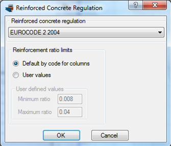
Selection of Eurocode 2 regulation
Definition of material properties
Next, we are going to specify the material properties.
Concrete can be specified by selecting Materials -> Concrete
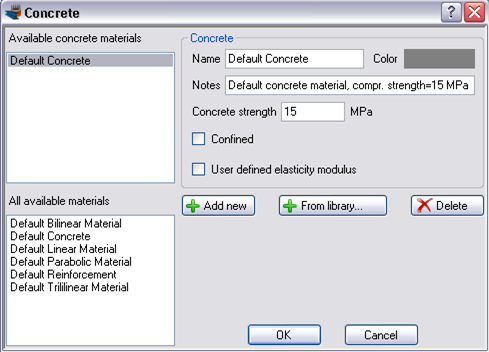
We click on “From library” button to import an existing concrete material from the database of the program.
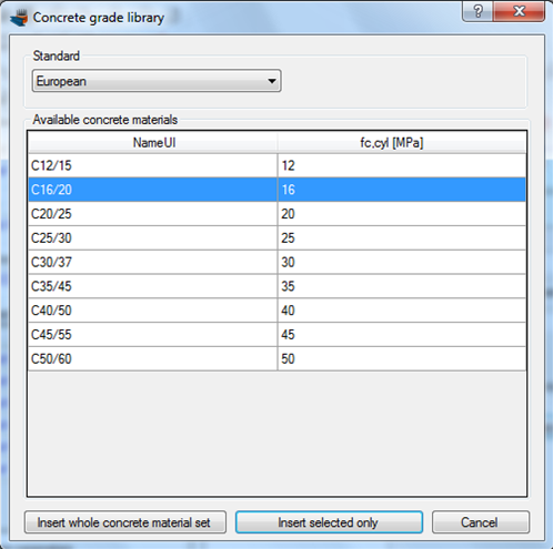
After choosing the European standard, we select the C16/20 material and click the “Insert selected only” button.
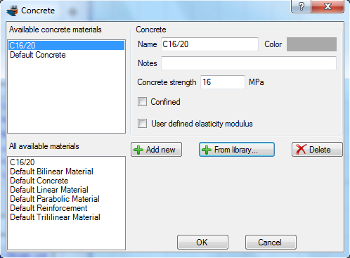
Since the material has been defined, we click OK to close the form.
The reinforcement can respectively be defined from the Material -> Reinforcement menu item. As before, we click the “From library” button to select from the existing predefined reinforcement materials.
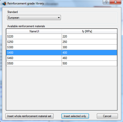
We choose the S400 grade from the European standard and click on “Insert selected only”.
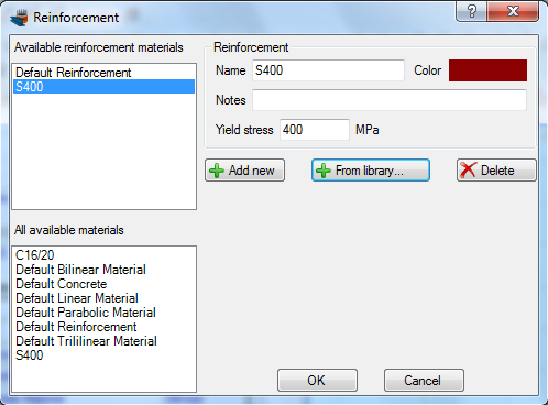
The reinforcement grade S400 is now available in the project.
Drawing the geometry
We are now ready to draw the geometry of the cross section, by clicking the Draw -> Rectangle using dimensions. The center point of the rectangular section can be inserted by entering its coordinates (0,0) and then clicking the  button, or just by clicking on the point (0,0) with the mouse. Then the Length and Width values should both be set to 0.40. Finally, the C16/20 concrete should be selected for the rectangle we are drawing.
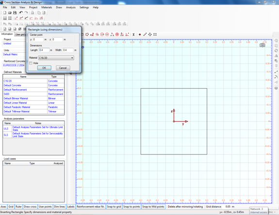
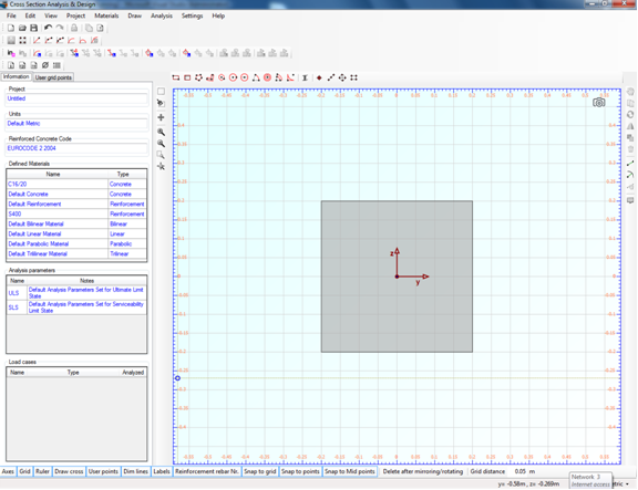
After we have clicked the “OK” button, the rectangle is shown in the drawing area.
Before drawing the rebars, we have to make sure that a proper rebar set is available for the design. This can be checked by selecting Project -> Available Rebars.
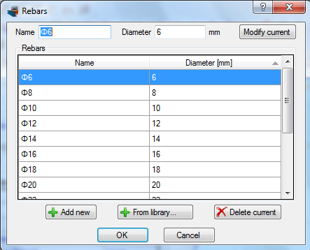
The rebars that are shown above are available in the project. This means that we can draw rebars of these diameters and additionally the program will only choose from these rebar sizes when performing a reinforcement design.
So, we can now draw the reinforcement bars by clicking on the Draw -> Rebar Rectangle menu item.
We can enter a value (0.04 m) for the reinforcement cover to the rebar center in the field, which becomes active when inserting reinforcement bars, as shown below. The program automatically draws help lines at the specified distance from the concrete rectangle edges and enables mouse snapping at their intersections.
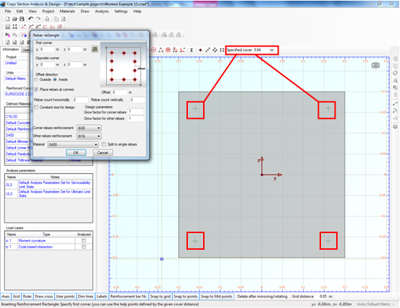
To draw the bottom rebars, we click on the green points at the top left and at the bottom right successively.
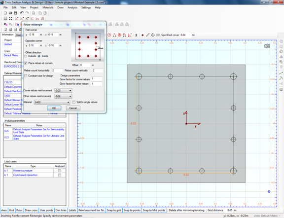
Next, as shown on the form below, we choose to use ø20 and ø16 rebar sizes for the corner and remaining rebars respectively. The rebar count (apart from the rebars at the corners) horizontally and vertically is set to 2.
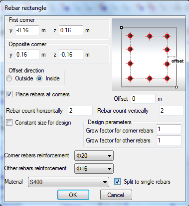
Moreover, the S400 reinforcement material is selected.
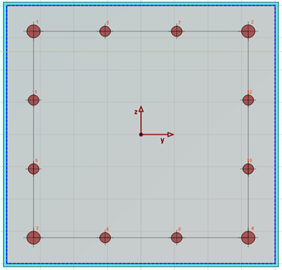
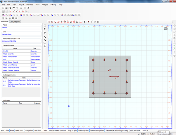
After clicking the “OK” button, the rebars are shown in the drawing area.
Behavior assessment of the cross section
First we are going to assess the behavior of the cross section by calculating a Moment vs. Curvature diagram for different axial force levels.
Review of Analysis Parameters
We need to specify the corresponding Analysis Parameters set by clicking Analysis -> Analysis Parameters. We will use the default “ULS” set.
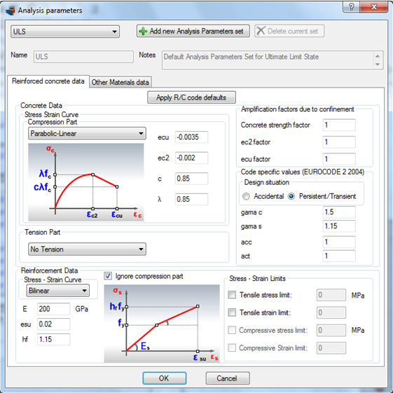
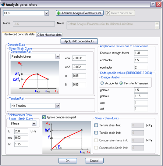
The option “Default rectangular by code for ULS” for the compressive parts of concrete stress/strain curve cannot be used, since we are about to perform a Moment Curvature analysis. “Default rectangular by code for ULS” option is only valid for designing or checking the capacity of a cross section.
So we choose the option “Parabolic-Linear”. The strain data have already been set by the program to their default values according to Eurocode 2.
All parameters related to Eurocode 2 can be found in this form, including partial safety factors etc.
The reinforcement bars are chosen to have a bilinear behavior. A hardening of 1.15 is assumed.
Additionally, we check the “Ignore compression part” in order to ignore the contribution of the reinforcement to the sectional resistance, i.e. steel reinforcement will only be active if it is under tension. This assumption is common, especially when retrofitting damaged concrete elements, as the sparse stirrups will not provide a lateral support to vertical reinforcement bars. Consequently their compressive resistance cannot be used due to buckling.
We click OK to close this form.
Definition of load cases
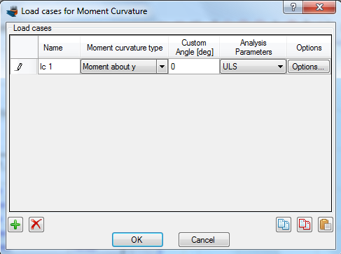
The load cases for Moment vs. Curvature analysis can be selected by clicking on the Analysis -> Moment Curvature -> Load cases menu item. By clicking the  button we can add a new load case. The Moment curvature type is set to “Moment about y”, the Custom Angle (coordinate system rotation) remains 0 and the Analysis Parameters item is changed to “ULS” in order to use the parameters defined previously.
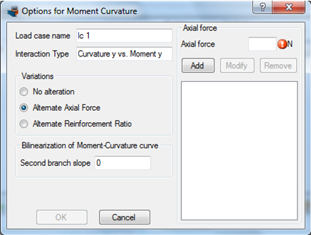
In order to use specific axial forces for the analysis, we click on “Options” button and as shown on the form below, we select the option “Alternate Axial Force”.
Next we enter the axial force values successively in the corresponding field at the top right corner of the form and click the “Add” button, so that all axial forces have been filled, as shown below.
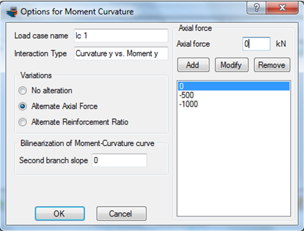
We can also define the slope of the second branch of the equivalent bilinearized curve here, but we keep this value equal to 0. This means that the calculated bilinearized curve will be elastic-fully plastic. We click OK to close the form.
Carry out the analysis
We just click Analysis -> Moment Curvature -> Analyze, to perform the reinforcement design procedure.
Results
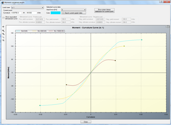
The calculated Moment – Curvature curves for the specified axial force levels can be found by clicking Analysis -> Moment Curvature -> Show results.
Behavior assessment after the application of steel jacket
Definition of a steel material
The steel grade of the jacket is assumed to be Fe 430. This steel grade can be imported from the library by clicking on the Materials -> Import from Library menu item. From the top list we select “Hot Rolled Steel – European (no hardening)” in order view the materials belonging to this collection.
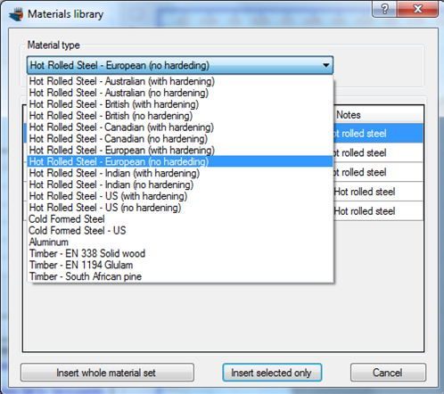
Then, we can select the corresponding row (Fe 430) and click on “Insert selected only” button to use this material in our project.
Drawing the steel jacket
The simplest way to draw the steel jacket geometry is to use the Draw -> Polygon from line offset.
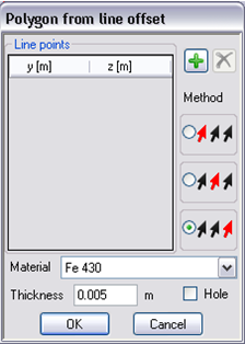
In the form that appears, we select the third option in the box “Method”. This will enable the drawing of the steel jacketing by just providing a path of points which are the 4 corners of the cross section. The specified thickness is set to 5 mm (0.005m) and current material is Fe 430.
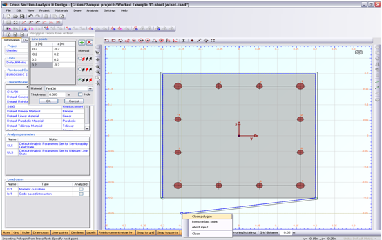
After successively clicking on the 4 corners of the cross section, we right-click at any point and choose “Close polygon” from the menu as shown above.
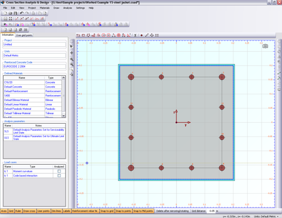
The retrofitted column section has been now defined. We can continue by reviewing the used Analysis Parameters set “ULS”.
Informing the program that the concrete is confined
This can be easily carried out by clicking the Materials -> Concrete menu item and checking the “Confined” option for C16/20 concrete grade, as shown below.
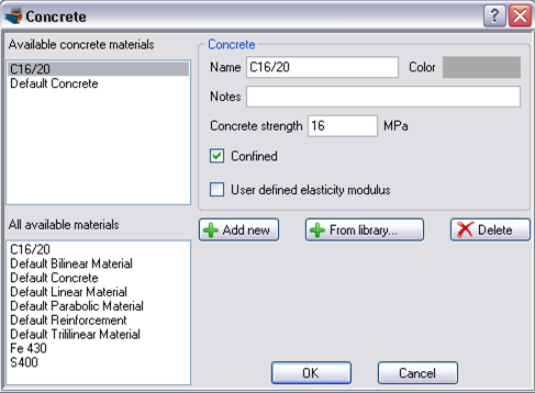
In this way, the program will handle the C16/20 concrete as defined, i.e. the confinement factors specified in Analysis Parameters will be applied to this material.
Review of Analysis Parameters
The Analysis Parameters set “ULS” will be modified in order to simulate the effect of steel jacketing on the behavior of the section.
Since the existing concrete is assumed confined, we can define the related amplification factors for its strength, the strain that corresponds to its strength and its ultimate strain. These values can be calculated according to any regulation or theoretical method and can be applied in the program.
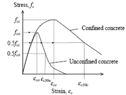
Example of confined and unconfined concrete stress/strain curves
In this example we will assume that the confined concrete stress is 21 MPa, with a corresponding strain of -3‰ and its ultimate strain is -7‰.
Consequently, the amplification factors can be calculated as follows:
| Concrete strength factor: | 21 MPa / 16 MPa | = 1.31 |
| ec2 factor: | 3‰ / 2‰ | = 1.5 |
| ecu factor: | 7‰ / 3.5‰ | = 1.5 |
All remaining data regarding concrete and reinforcement do not need to be modified.
Furthermore, in tab “Other Materials data”, we can define a partial safety factor for the steel jacketing, which is taken as 1.15.
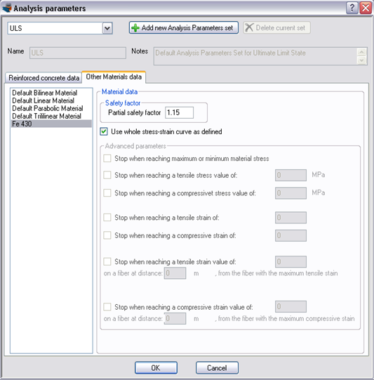
We click OK to close this form.
Carry out the analysis of the retrofitted section
We just click Analysis -> Moment Curvature -> Analyze, to perform the reinforcement design procedure.
Results
The calculated Moment – Curvature curves for the specified axial force levels can be found by clicking Analysis -> Moment Curvature -> Show results.
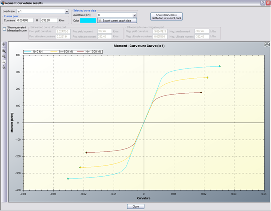
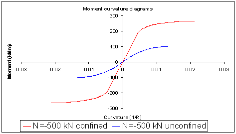
As expected, after the application of the steel jacket, the cross section behavior in terms of stiffness, resistance and ductility has dramatically been improved.
By clicking the “Export current graph data”, we can export the points of selected diagram to a text file and use them in other applications, such as Excel. In the following graph, the Moment vs. Curvature curves before and after the retrofit are shown for the same axial force load (-500 kN).