Example 9: Check of user-defined reinforcement pattern in a composite cross section of a column
Watch the video of this example >
Data for Cross Section Analysis & Design application
In this example we are going to create the geometry of a composite cross section, define rebars and check their capacity according to Eurocode 2.
Regulation: Eurocode 2
Concrete (cylinder) strength: 20 MPa
Yield stress of reinforcement steel: 500 MPa
Reinforcement cover to rebar center: 4 cm
Steel grade: Fe 360
Tensile concrete strength is ignored.
Stirrup type: Tied
All remaining data (safety factors, other coefficients etc.) to be taken according to Eurocode 2.
Load cases
| lc 1 | N = -1000 kN | My = 550 kNm | Mz = 123 kNm |
| lc 2 | N = -770 kN | My = 140 kNm | Mz = -365 kNm |
Solution with Cross Section Analysis & Design
First of all define the corresponding Reinforced Concrete Code, by clicking on the Project -> Reinforced Concrete Code menu item.
Selection of Reinforced Concrete Code
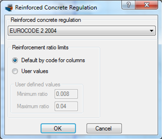
Selection of Eurocode 2 regulation
The reinforcement ratio limits are to be calculated according to Eurocode 2, so we keep the default option checked.
Definition of material properties
Next, we are going to specify the material properties.
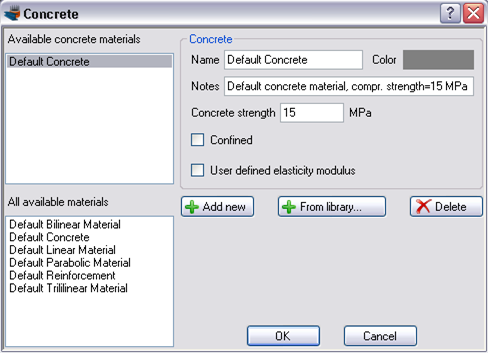
Concrete can be specified by selecting Materials -> Concrete
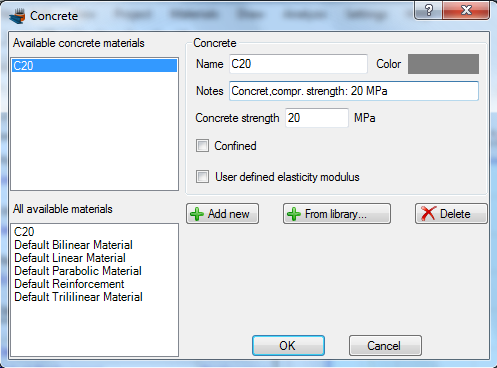
The Default Concrete material can be overridden by changing its properties, as shown in the form below.
Value “Concrete strength” has been set equal to 20 MPa. The concrete is not assumed confined and the elasticity modulus is to be calculated according to Eurocode 2, so we do not need to change anything else. The concrete defined here is now accessible through the name “C20”. Alternatively we could click the “Add new” button in order to define a new concrete material.
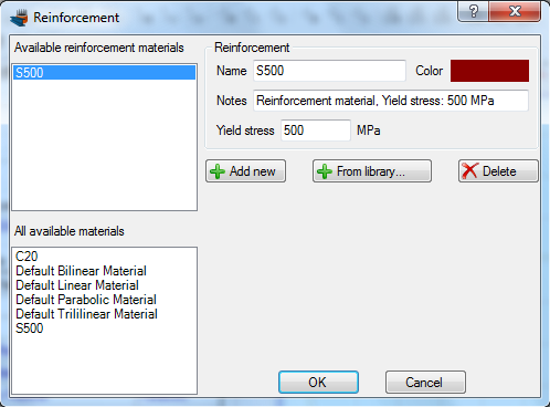
The reinforcement can respectively be defined from the Material -> Reinforcement menu item.
We modify the Default Reinforcement material by specifying a new name (S500) and a yield stress of 500 MPa.
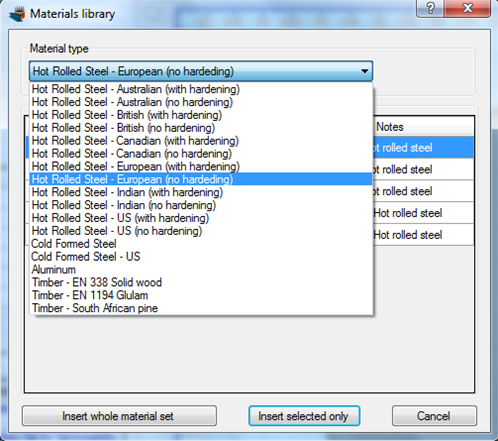
Finally we need to define the grade of the steel Fe 360. This steel grade can be imported from the library of the program by clicking on the Materials -> Import from Library menu item. From the top list we select “Hot Rolled Steel – European (no hardening)” in order to view the materials belonging to this collection.

Then, we can select the first row (Fe 360) and click on “Insert selected only” button to use this material in our project.
Fe 360 steel has been imported in our project. We can view/change its properties by clicking on it from the list of the main form, as shown in the picture below.
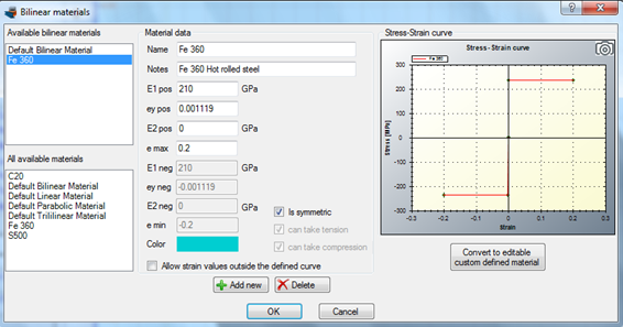
Alternatively, as Fe 360 steel is as bilinear material, it can be edited from the Materials -> Bilinear Materials menu item.
In this form, the stress/strain curve of Fe 360 hot rolled steel is represented. We do not need to change anything and click OK.
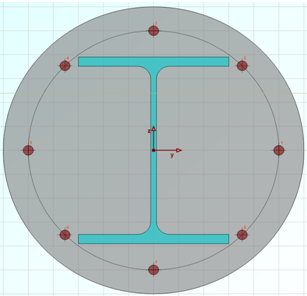
Drawing the geometry
We are now ready to draw the geometry of the cross section, by clicking the Draw -> Circle (2Points).
First of all we make sure that material “C20” has been selected in the shown form.
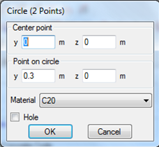
Then, we can specify the center point of the circle by entering its coordinates (0,0) and then clicking the  button, or just by clicking on the point (0,0) with the mouse.
After that we need to define one point on the circle. This can be done by clicking at the point (0.30,0).
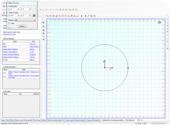
So, the circle is now defined and we can see it in the drawing area.
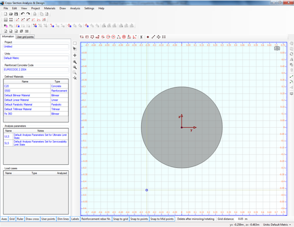
We can modify its properties by moving the mouse over it, right clicking and selecting “Properties” from the corresponding menu.
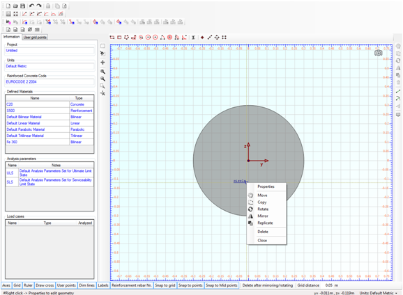
In this way, the “Circle” form is shown and we can view/change its data.
Afterwards, we can insert a hot rolled section from the library by clicking the Draw -> Standard Section menu item.
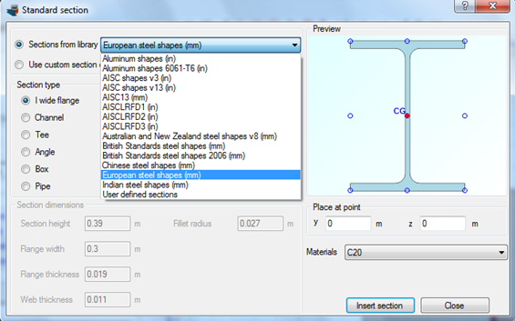
In this form, the collections of all sections of the library are represented. In order to insert a HEA-400 cross section, we select “European steel shapes” from the top list and then we choose the “HE400A” shape from the list below.
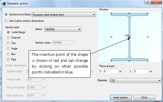
The insertion point of the shape is selected to coincide with its centroid.
We should not forget to change the material for this section to Fe 360, as illustrated below.
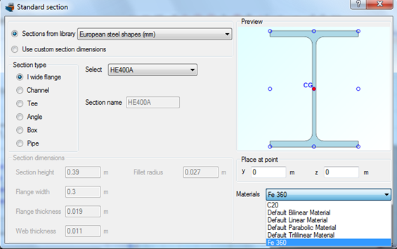
We click OK and see that the steel shape is shown in the main drawing area.
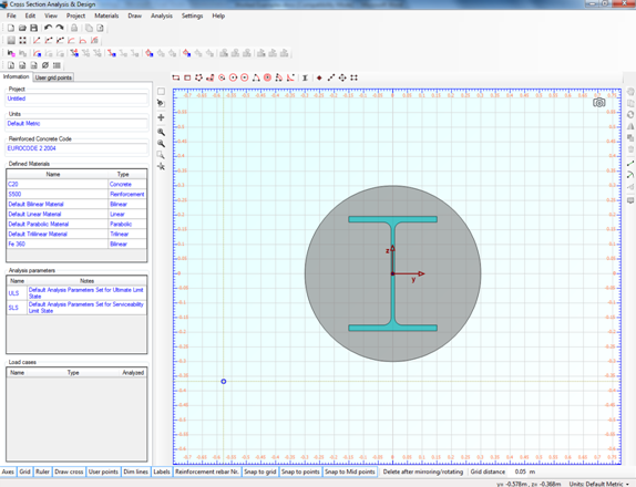
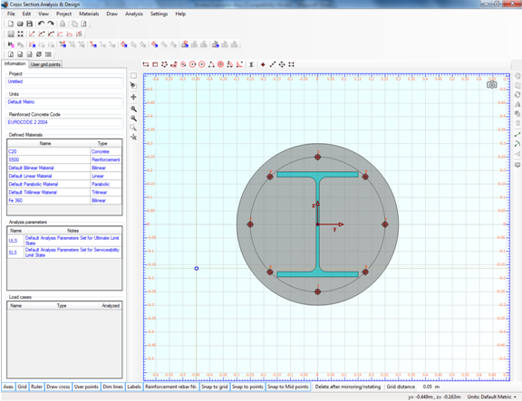
Furthermore, we need to draw the rebars, which will have a circular pattern.
But first let’s see if rebar sizes are defined. We select Project -> Available Rebars.
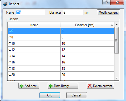
The rebars shown above are available in the project. This means that we can draw rebars of these diameters and additionally the program will only choose from these rebar sizes when performing a reinforcement design.
Now we are ready to draw the reinforcement bars by clicking on the Draw -> Rebar Circle menu item.
We can enter a value (0.05 m) for the reinforcement cover to the rebar center in the field, which becomes active when inserting reinforcement bars, as shown below. The program automatically draws help points at the specified distance from the concrete edges and enables mouse snapping.
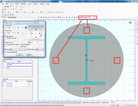
To draw the rebars, we click on (0,0) point and then on one of the available green points.
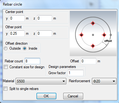
We change the rebar count to 8 and also check that the reinforcement material is “S500” and choose a rebar size, ø20.
After clicking the “OK” button, the lower rebars are shown in the drawing area.
Review of Analysis Parameters
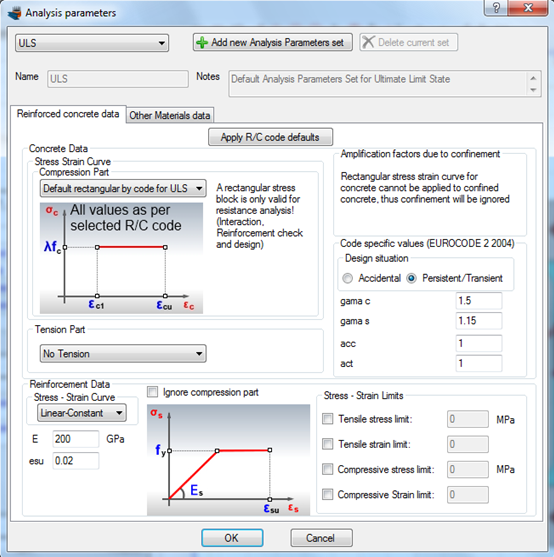
We need to specify the corresponding Analysis Parameters set by clicking Analysis -> Analysis Parameters. We will use the default “ULS” set. All parameters related to Eurocode can be found in this form. The concrete stress block is rectangular according to Eurocode 2 parameters, the tensile resistance of concrete is ignored and all remaining data have the default values. You can override these values by modifying any of the field of the form.
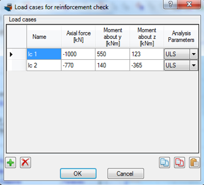
Definition of load cases
The load cases can be selected by clicking on the Analysis -> Reinforcement check -> Load cases menu item. The 2 load cases can be entered in the corresponding table. A new load case can be inserted by clicking the  button. We make sure that the assigned Analysis Parameters set to each load case is ULS.
Reinforcement check
We just click Analysis -> Reinforcement check -> Analyze, to perform the reinforcement design procedure.
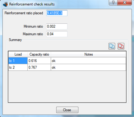
Results
The results can be obtained from the Analysis -> Reinforcement check -> Show results menu item.
As we can see, the cross section is adequate for both load cases. This form reports the placed reinforcement ratio (9.42 ‰) which lies between the allowable limits (2‰ – 4%) calculated according to Eurocode 2 specifications.
Watch the video of this example