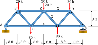
Methods of Simple Truss Analysis
2020-10-03

General information
- A truss structure is composed of slender members joined together at their end points
- Members are commonly wooden struts or metal bars
- Joint connections are formed by bolting or welding the ends of the members to a common plate (gusset plate) or by simply passing a large bolt or pin through each of the members
- Planar trusses lie in a single plane (often seen supporting roofs and bridges), 2-D analysis of forces appropriate
1. Truss Analysis Method of joints
- If a truss is in equilibrium, then each of its joints must also be in equilibrium
- The method of joints consists of satisfying the equilibrium conditions for the forces exerted “on the pin” at each joint of the truss
- Truss members are all straight two-force members lying in the same plane
- The force system acting at each pin is coplanar and concurrent (intersecting)
- Rotational or moment equilibrium is automatically satisfied at the joint, only need to satisfy
- ∑ Fx = 0, ∑ Fy = 0
- Draw the free-body diagram of a joint having at least one known force and at most two unknown forces (may need to first determine external reactions at the truss supports)
- Establish the sense of the unknown forces
- Always assume the unknown member forces acting on the joint’s free-body diagram to be in tension (pulling on the “pin”)
- Assume what is believed to be the correct sense of an unknown member force
- In both cases a negative value indicates that the sense chosen must be reversed
- Orient the x and y axes such that the forces can be easily resolved into their x and y components
- Apply ∑ Fx = 0 and ∑ Fy = 0 and solve for the unknown member forces and verify their correct sense
- Continue to analyze each of the other joints, choosing ones having at most two unknowns and at least one known force
- Members in compression “push” on the joint and members in tension “pull” on the joint
- Mechanics of Materials and building codes are used to size the members once the forces are known
Zero-force members
- Truss analysis using the method of joints is greatly simplified if one is able to determine those members which support no loading (zero-force members)
- These zero-force members are used to increase stability of the truss during construction and to provide support if the applied loading is changed
- If only two members form a truss joint and no external load or support reaction is applied to the joint, the members must be zero-force members
- If three members form a truss for which two of the members are collinear, the third member is a zero-force member provided no external force or support reaction is applied.
2. Method of sections for trusses
Based on the principle that if a body is in equilibrium, then any part of the body is also in equilibrium.
Procedure for analysis
- Section or “cut” the truss through the members where the forces are to be determined
- Before isolating the appropriate section, it may be necessary to determine the truss’s external reactions (then 3 equations equations of equilibrium can be used to solve for unknown member forces in the section)
- Draw the free-body diagram of that part of the sectioned truss that has the least number of forces acting on it
- Establish the sense of the unknown member forces
- Apply 3 equations of equilibrium trying to avoid equations that need to be solved simultaneously
- Moments should be summed about a point that lies at the intersection of the lines of action of two unknown forces
- If two unknown forces are parallel – sum forces perpendicular to the direction of these unknowns
Frames and Machines
- Structures are often composed of pin-connected multi force members
- Frames are generally stationary and are used to support loads
- Machines contain moving parts and are designed to transmit and alter the effect of forces
- Can apply the equations of equilibrium to each member of the frame or machine to determine the forces acting at the joints and supports (assuming the frame or machine is properly constrained and contains no more supports or members than are necessary to prevent collapse)
- Construct applicable free-body diagrams
- Draw an outline of the shape
- Show all forces or couple moments that act on the part
- Indicate dimensions needed for determining moments
- Identify all two force members in the structure
- All loadings are applied at the joint
- Members are joined together by smooth pins
- Members have two equal but opposite forces acting at their points of application
- The line of action of the forces are along the axis of the members
- Forces common to any two contacting members act with equal magnitudes but opposite sense on the respective members
- Apply the equations of equilibrium
Our software 2D Frame Analysis - Truss Edition can effectively analyze and kind of structural truss, calculate and represent its internal force diagrams as well as nodal displacements and create a ready-to-submit calculation report.
Source: aboutcivil.org/simpl-truss-analysis-methods.html
